Demystify jumpers
Jifang industrial control with you to uncover the mystery of jumper veil
Believe many friends looking at rows and rows of introduction to computer jump line will feel headaches brain swelling, don't know how to start, remember the first time in the computer city assembling computer, to see technicians take light put good graphics card is inserted in the motherboard, memory and CPU, etc., and then took out a key on the edge of the motherboard so gently touch, the miracle appear, CPU fan turn up, the computer that took the boot, let a lot of friends all stunned; Random piece of new motherboard, in their hands within a few minutes can be connected to the motherboard that dense jumpers, looks so skilled high-end professional, give a person a sense of hope and retreat; Today jifang industrial control sorted out some of the jumper connection skills, some of the rules and experience summarized for many people are very useful, in a careful reading, a simple note, I believe also can become a jumper master, at least will not be mysterious and complex and difficult to understand the jumper by the trouble.
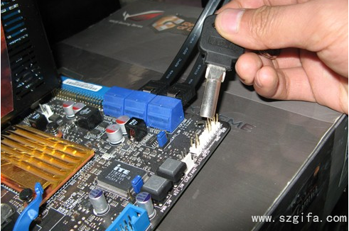
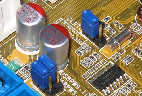
Before you begin to understand what is a jump line, in fact it is not the case that their line above, nor g-kong motherboard the rows need connection pin (this can only be called quilt connection socket), but the two or three pin, top with a small "jumpers" that should be called "jump", it can play the role of hardware change Settings, frequency, etc. The following figure
Do you have a headache when you see the handful of wires in the chassis? Follow our rhythm, you will find that it is so simple, all small cases.
The cables in the chassis is the channel connecting the main box and motherboard jump line, so that we can jump line from outside chassis control functions, to shutdown restart and some other basic function, so let's start with the cables in the case, this is quite simple, above the line by the word notes, we remember slightly with respect to OK, here we list them, by cooperating with convenient memory.
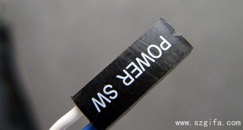
1. POWER SWITCH, this is POWER SW, the POWER button in front of the chassis. Its full name is POWER Swicth.
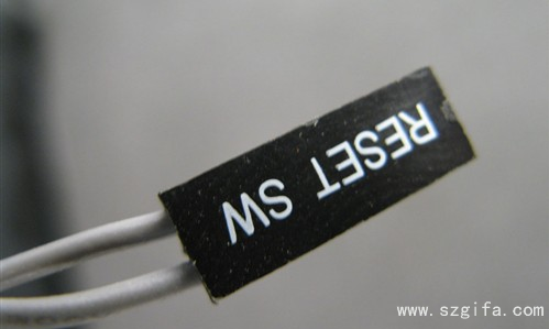
2.RESET/restart switch. The RESET button in front of the chassis is RESET SW, which is next to the power switch. Its full name is RESET Swicth.
3. POWER indicator: +/-, likely name: POWER LED, PLED, PWR LED, SYS LED, etc
The status indicator of the Hard disk: HDD LED, whose full English name is: Hard disk drive light emitting module, possibly with the name HD LED
Function definition: abnormal working alarm of the main board. Needless to say, those connected to the front USB port are generally integrated
6. AUDIO connector: AUDIO, possible name: FP AUDIO, function definition: chassis front AUDIO
Is not very easy ah, in fact, is a few very simple English abbreviations, the next key, we come to understand the motherboard "jumper".
Here we pay attention to, there are a lot of rules are summed up after we remember to be able to draw a conclusion, no matter what brand of motherboard do not have to see the manual insert a good complex jumper.
1. How about the first Pin on the jumper line?
We must know how to count the first pin of the jumper, it is not difficult to find that on the motherboard (any board card device is the same), there is always a thick printing box at one end of the jumper, and the jumper should be counted from here. Once you find the thicker print box, follow the left to right, top to bottom rule. Let's take a closer look at the picture below.
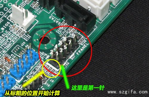
2. Know the definition of 9Pin switch/reset/power lamp/hard disk lamp
At present, many mainboards are the jumpers of 9pin, and many mainboards of jisquare industrial control are of this kind. We must understand this. From the figure above, we can see that the last 9pin is not defined at all, so it is not necessary to insert this one when inserting the jumpers. Let's follow the diagram. It's easy. Note that the Power SW and reset switches (both of which do not divide the positive and negative poles), and the two indicator lights need to distinguish the positive and negative poles, the positive pole is connected in the direction close to the first pin (that is, the direction of the printed thick line). Generally, colored lines are positive, while black/white lines are negative (ground, sometimes referred to as GND).
Here actually read understand to be able to connect almost good line, found a popular 4 sentences on the net to generalize, achieve relaxed memory. 9Pin defines the position of switch/reset/power lamp/hard disk lamp.
1. Insert power supply next to the missing needle
2, the opposite side of the power plug reset
3. Power lamp is inserted next to the power supply, and the negative pole is close to the power jumper
4. Insert hard disk lamp beside the reset, and the negative pole is close to the reset jumper wire
That said, I believe you must remember!
3. Some brands of motherboard jumper may be connected with different methods, here we list separately, also can understand once look. Like this asus one.

This is a schematic diagram of the wiring of asus motherboard (the red dots indicate no pins).
So let's see what the pattern is. First of all, the rule is most obvious in speakers. The four pins are together, so you cannot insert anything else except the SPEAKER. So when we see such pins in the future, we first determine the position of the SPeaker. Then, if there are 3 pins together, it must be connected to the power indicator, because only the power indicator may appear 3Pin; Third, 90% of the Power switches are independent of the two pins in the middle. Of course, you can also connect these two pins with a conductor by yourself. If Power is turned on, it is proved to be Power. The rest of course is to insert the hard disk light, pay attention to the power indicator and the hard disk working status indicator is to be divided into positive and negative, in fact, the reverse is nothing, but will not light, will not cause damage to the motherboard.
4 finally have the first jifang industrial control net friends will ask, there are a lot of no rules of the motherboard jumper, in fact, other rules, but is not very obvious, here we just look at the wiring on the logo, combined with the above method according to the logo to plug the line, can be easily solved.
5. The front USB
It's very simple, it's usually integrated for us, just plug it in,
Now the general chassis of the front USB connection search is integrated, there are a total of 8 cables, VCC, Data+, Data-, GND, this integration does not need to say more, directly plug on the line. If they are separate, they are usually connected in the order of red, white, green and black. This line, like the one above, although integrated, is also sorted in red, white, green and black.
6. Pre-audio connection method
This is actually a lot of lines, but it's super easy, we just have to remember a few roots,
The sorting of pre-audio pins has become a fixed standard. There are 9 pins in the pre-audio, but they occupy 10 pins in total. The 8th pin is left empty.
A typical pre-audio connection, the pre-audio actually only needs to be connected to 7 wires, which is the 7 wires in the figure above. In the motherboard pin end, as long as we understand the definition of each pin, it is also very easy to connect the pre audio. Below let's look at the definition of each needle on the motherboard:
1 -- Mic in/ Mic (Mic input)
2 -- GND (ground)
3 -- Mic Power/Mic VCC/ Mic BIAS
4 - No pin
5 -- LINE OUT FR (right channel pre-audio output)
6 -- LINE OUT RR (right channel rear audio output)
7 - NO pin
8 -- NO pin
9 -- LINE OUT FL (left channel front audio output)
10 -- LINE OUT RL (for channel post-audio output)
It looks like a little bit too many lines, but it's also very easy to remember, so you might as well do it the way I did it. First remember the first three, the first is the mic input, the second is the ground, the third is the mic voltage, and then the 5th and 6th pin are inserted in the right channel, and the 9th and 10th pin are inserted in the left channel. Mic in, Mic voltage, right channel, left channel, plus a ground.
Now a lot of industrial control motherboard jumpers have given us integration, more relaxed than before, ji fang industrial control this time to provide you with these rules and experience skills, I hope we become master master. This article has jifang industrial control exclusive sorting and editing, welcome all users reproduced.


